Sistemas Embebidos

Julio Cesar Cardona Diaz MSP430
Proyecto final
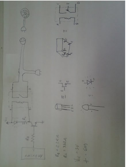
Como proyecto final se creó una interfaz web que puedo ser accedida desde cualquier dispositivo que tenga un navegador web entre estos podemos encontrar celulares y pc; a través de esta interfaz se encenderá y apagara un dispositivo eléctrico que funcione con corriente alterna de 110 v.
Por ultimo esta interfaz tiene como requerimiento un sistema de autenticacion, para que no se manipulado por estraños
Por ultimo esta interfaz tiene como requerimiento un sistema de autenticacion, para que no se manipulado por estraños
proyecto final
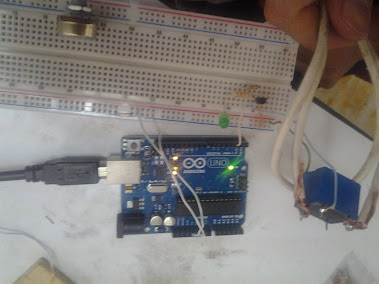
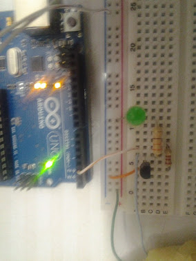
circuito del proyecto final
proyecto vista 1
proyecto vista 2
programa del arduino
int p=2;
void setup(){
pinMode(p, OUTPUT);
Serial.begin(9600);
}
void loop(){
//si esta habilitado la salida de datos en el buffer del puerto
if (Serial.available() > 0) {
int s = Serial.read()-48;
digitalWrite(p,s);
Serial.println(s);
}//fin if
}//fin loop
progrma en php
< !--?php
session_start();
if($_session[level] == 1)
{
//echo 'Tienes level 1 y puedes ver esta página';
}else{
header("Location: index.php");
}
?-- >
< !--?php
if(!$_post[enviar]){
$descriptorfichero = file("datos.txt");
$_post[estado_equipo]=$descriptorfichero[0];
}//fin if
if($_post[enviar]){
#abrimos el fichero en modo de escritura
$descriptorfichero = fopen("datos.txt","w");
#escribimos la primera línea dentro de él
fputs($descriptorfichero,$_post[estado_equipo]);
#cerramos el fichero
fclose($descriptorfichero);
$descriptorfichero = file("datos.txt");
$_post[estado_equipo]=$descriptorfichero[0];
}
?-- >
< form name="formulario" id="formulario" action="equipo.php" method="POST" >
" size="30">
< input name="enviar" value="1" size="30" type="hidden" / >
< br / >
" onClick="javascript:document.formulario.submit()" alt="some_text"/>
< /form >
< br / >< a href="logout.php" >Salir< /a >< !--?php-- >< !--?php
session_start();
if($_session[level]-- >
programa java
import java.util.List;
import giovynet.nativelink.SerialPort;
import giovynet.serial.Baud;
import giovynet.serial.Com;
import giovynet.serial.Parameters;
public class hiloRunnable implements Runnable {
Thread hilo;
SerialPort serialPort;
Parameters parameters;
Com com;
public hiloRunnable(String name) throws Exception {
hilo = new Thread(hiloRunnable.this);
hilo.setName(name);
serialPort = new SerialPort();
parameters = new Parameters();
parameters.setPort("COM6");
parameters.setBaudRate(Baud._9600);
com = new Com(parameters);
}
@Override
public void run() {
//for (int i = 0; i < 50; i++) {
while (true) {
try {
hilo.sleep(1000);
try {
String[] arrArray = LeerArchivos.leerArchivo("D:/wamp/www/pFinal/datos.txt", 0);
com.sendSingleData(arrArray[0]);
} catch (Exception e) {
// TODO Auto-generated catch block
e.printStackTrace();
}
// System.out.println("Yo soy "+hilo.getName());
} catch (InterruptedException e) {
// System.out.println("el hilo se cayo intentando dormir");
}
}
/*try {
com.close();
} catch (Exception e) {
// TODO Auto-generated catch block
e.printStackTrace();
}*/
}
public void start() {
this.hilo.start();
}
}
Comprar LaunchPad de Texas Instrument
en la pagina http://www.plintec.com.co/ su precio es de $29.000 pesos
Como comenzar
deberas descargar
MSP430_LaunchPad_Workshop.exe (estos son ejemplos)
slac050ag.zip (este es IAR Embedded Workbench)
LaunchPad.pdf (guia de inicio)
estos archivos y muchos mas los encontraras en la pagina oficial http://www.ti.com/
una ves instalado podras conectar tu msp430 y sera reconocido como un puerto COM y tambien podras usar el IAR EMBEDDED
Administrador de dispositivos
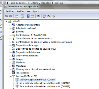
msp430 aplication uart com4
IAR Embedded Workbench
software
4 leds en secuencia
4 leds en secuencia
#include "io430.h"
void delay( void){
volatile unsigned int i;
for (i=0;i<60000;i++);
}
int main( void )
{
// Stop watchdog timer to prevent time out reset
WDTCTL = WDTPW + WDTHOLD; // Stop watchdog timer
P1DIR |= BIT5; // Set P1.0 to output direction
P1DIR |= BIT4;
P1DIR |= BIT6;
P1DIR |= BIT7;
for (;;)
{
volatile unsigned int i; // volatile to prevent optimization
P1OUT ^= BIT5; // Toggle P1.0 using exclusive-OR
delay();
P1OUT ^= BIT4;
delay();
P1OUT ^= BIT6;
delay();
P1OUT ^= BIT7;
delay();
i = 10000; // SW Delay
do i--;
while (i != 0);
}
}
potenciometro y 4 leds
potenciometro y 4 leds
#include "msp430g2231.h"
#define LED0 BIT5
#define LED1 BIT4
#define LED2 BIT6
#define LED3 BIT0
unsigned int value=0;
void ConfigureAdc(void)
{
/* Configure ADC Channel */
ADC10CTL1 = INCH_7 + ADC10DIV_3 ; // Channel 7, ADC10CLK/4
ADC10CTL0 = SREF_0 + ADC10SHT_3 + ADC10ON + ADC10IE; //Vcc & Vss as reference
ADC10AE0 |= BIT7; //P1.7 ADC option
}
void main(void)
{
WDTCTL = WDTPW + WDTHOLD; // Stop WDT
BCSCTL1 = CALBC1_1MHZ; // Set range
DCOCTL = CALDCO_1MHZ;
BCSCTL2 &= ~(DIVS_3); // SMCLK = DCO = 1MHz
P1DIR |= LED0 + LED1 +LED2 + LED3;
P1SEL |= BIT7; //ADC Input pin P1.7
P1OUT &= ~(LED0 + LED1+LED2 + LED3);
ConfigureAdc();
__enable_interrupt(); // Enable interrupts.
while(1)
{
__delay_cycles(10000); // Wait for ADC Ref to settle
ADC10CTL0 |= ENC + ADC10SC; // Sampling and conversion start
__bis_SR_register(CPUOFF + GIE); // LPM0 with interrupts enabled
value = ADC10MEM;
if (value>476 && value<492)
{
P1OUT &= ~(LED0 + LED1 + LED2 + LED3);
P1OUT |= LED0;
}else{
if (value>494 && value<507)
{
P1OUT &= ~(LED0 + LED1 + LED2 + LED3);
P1OUT |= LED1;
}else{
if (value>509 && value<523)
{
P1OUT &= ~(LED0 + LED1 + LED2 + LED3);
P1OUT |= LED2;
}else{
if (value>525 && value<541)
{
P1OUT &= ~(LED0 + LED1 + LED2 + LED3);
P1OUT |= LED3;
}
}
}
}
}//while
}
// ADC10 interrupt service routine
#pragma vector=ADC10_VECTOR
__interrupt void ADC10_ISR (void)
{
__bic_SR_register_on_exit(CPUOFF); // Return to active mode
}
2 potenciometros y 4 leds
2 potenciometros y 4 leds
#include "msp430g2231.h"
#define LED0 BIT3
#define LED1 BIT0
#define LED2 BIT7
#define LED3 BIT6
unsigned int icanal=0;
unsigned short value1=0;
unsigned short value2=0;
unsigned int value3=0;
void ConfigureAdc()
{
/* Configure ADC Channel */
if(icanal==4) ADC10CTL1 = INCH_4 + ADC10DIV_3 ; // Channel 5, ADC10CLK/4
if(icanal==5) ADC10CTL1 = INCH_5 + ADC10DIV_3 ; // Channel 5, ADC10CLK/4
}
void leer(){
//unsigned short alg0=0;
ADC10CTL0 &= ~ENC;
ConfigureAdc();
ADC10CTL0 |= ENC + ADC10SC; // Sampling and conversion start
}
void main(void)
{
WDTCTL = WDTPW + WDTHOLD; // Stop WDT
BCSCTL1 = CALBC1_1MHZ; // Set range
DCOCTL = CALDCO_1MHZ;
BCSCTL2 &= ~(DIVS_3); // SMCLK = DCO = 1MHz
ADC10CTL0 = SREF_0 + ADC10SHT_3 + ADC10ON;
// Sample-and-hold ADC10SC bit, ADC10 Clock /1, ADC10 Source Clock, Single Channel Conversion
ADC10CTL1 = SHS_0 + ADC10DIV_0 + ADC10SSEL_0 + CONSEQ_0;
ADC10AE0 = BIT4 + BIT5;
//preparar leds
P1DIR |= LED0 + LED1 +LED2 + LED3;
P1OUT &= ~(LED0 + LED1+LED2 + LED3);
while(1)
{
__delay_cycles(10000); // Wait for ADC Ref to settle
__enable_interrupt(); // Enable interrupts.
volatile unsigned int i;
icanal=4;
leer();
value1 = ADC10MEM + 0;
if (value1>450 && value1<485)value3=1;
if (value1>490 && value1<505)value3=2;
if (value1>510 && value1<531)value3=3;
if (value1>533 && value1<580)value3=4;
P1OUT &= ~(LED0 + LED1+LED2 + LED3);
if(value3==1)for (i=0;i<60000;i++);
if(value3==2){for (i=0;i<60000;i++);for (i=0;i<60000;i++); }
if(value3==3){for (i=0;i<60000;i++);for (i=0;i<60000;i++);for (i=0;i<60000;i++); }
if(value3==4){for (i=0;i<60000;i++);for (i=0;i<60000;i++);for (i=0;i<60000;i++);for (i=0;i<60000;i++); }
icanal=5;
leer();
value2 = ADC10MEM + 0;
/////////////////////////////////////////////////////
if (value2>450 && value2<485)
{
P1OUT = LED0;
if(value3==1)for (i=0;i<60000;i++);
if(value3==2){for (i=0;i<60000;i++);for (i=0;i<60000;i++); }
if(value3==3){for (i=0;i<60000;i++);for (i=0;i<60000;i++);for (i=0;i<60000;i++); }
if(value3==4){for (i=0;i<60000;i++);for (i=0;i<60000;i++);for (i=0;i<60000;i++);for (i=0;i<60000;i++); }
}else{
if (value2>490 && value2<505)
{
P1OUT = LED1;
if(value3==1)for (i=0;i<60000;i++);
if(value3==2){for (i=0;i<60000;i++);for (i=0;i<60000;i++); }
if(value3==3){for (i=0;i<60000;i++);for (i=0;i<60000;i++);for (i=0;i<60000;i++); }
if(value3==4){for (i=0;i<60000;i++);for (i=0;i<60000;i++);for (i=0;i<60000;i++);for (i=0;i<60000;i++); }
}else{
if (value2>510 && value2<525)
{
P1OUT = LED2;
if(value3==1)for (i=0;i<60000;i++);
if(value3==2){for (i=0;i<60000;i++);for (i=0;i<60000;i++); }
if(value3==3){for (i=0;i<60000;i++);for (i=0;i<60000;i++);for (i=0;i<60000;i++); }
if(value3==4){for (i=0;i<60000;i++);for (i=0;i<60000;i++);for (i=0;i<60000;i++);for (i=0;i<60000;i++); }
}else{
if (value2>530 && value2<580)
{
P1OUT = LED3;
if(value3==1)for (i=0;i<60000;i++);
if(value3==2){for (i=0;i<60000;i++);for (i=0;i<60000;i++); }
if(value3==3){for (i=0;i<60000;i++);for (i=0;i<60000;i++);for (i=0;i<60000;i++); }
if(value3==4){for (i=0;i<60000;i++);for (i=0;i<60000;i++);for (i=0;i<60000;i++);for (i=0;i<60000;i++); }
}
}
}
}
/////////////////////////////////////////////////////
}//while
}
// ADC10 interrupt service routine
#pragma vector=ADC10_VECTOR
__interrupt void ADC10_ISR (void)
{
__bic_SR_register_on_exit(CPUOFF); // Return to active mode
}
enviar datos por seria con msp430
//***********************************************************
// Lab7.c Software UART
//
// SFB 10/2010
//***********************************************************
#include
#define TXD BIT1 // TXD on P1.1
#define RXD BIT2 // RXD on P1.2
#define Bitime 13*4 // 0x0D
unsigned int TXByte;
unsigned char BitCnt;
unsigned int TxJULIO[]={0x4A,0x55,0x4C,0x49,0x51,0x3B};
volatile long tempRaw;
volatile long tempSet = 0;
volatile int i;
void FaultRoutine(void);
void ConfigWDT(void);
void ConfigClocks(void);
void ConfigPins(void);
void ConfigADC10(void);
void ConfigTimerA2(void);
void Transmit(void);
void main(void)
{
ConfigWDT();
ConfigClocks();
ConfigPins();
ConfigADC10();
ConfigTimerA2();
while(1)
{
_bis_SR_register(LPM3_bits + GIE); // turn on interrupts and LPM3
for (i=0;i<6;i++)
{
TXByte = TxJULIO[i];
Transmit();
}
}
}
void ConfigWDT(void)
{
WDTCTL = WDT_ADLY_250; // <1 sec WDT interval
IE1 |= WDTIE; // Enable WDT interrupt
}
void ConfigClocks(void)
{
if (CALBC1_1MHZ ==0xFF || CALDCO_1MHZ == 0xFF)
FaultRoutine(); // If calibration data is erased
// run FaultRoutine()
BCSCTL1 = CALBC1_1MHZ; // Set range
DCOCTL = CALDCO_1MHZ; // Set DCO step + modulation
BCSCTL3 |= LFXT1S_2; // LFXT1 = VLO
IFG1 &= ~OFIFG; // Clear OSCFault flag
BCSCTL2 = 0; // MCLK = DCO = SMCLK
}
void FaultRoutine(void)
{
P1OUT = BIT0; // P1.0 on (red LED)
while(1); // TRAP
}
void ConfigPins(void)
{
P1SEL |= TXD + RXD; // P1.1 & 2 TA0, rest GPIO
P1DIR = ~(BIT3 + RXD); // P1.3 input, other outputs
P1OUT = 0; // clear output pins
}
void ConfigADC10(void)
{
ADC10CTL1 = INCH_10 + ADC10DIV_0; // Temp Sensor ADC10CLK
}
void ConfigTimerA2(void)
{
CCTL0 = OUT; // TXD Idle as Mark
TACTL = TASSEL_2 + MC_2 + ID_3; // SMCLK/8, continuos mode
}
// WDT interrupt service routine
#pragma vector=WDT_VECTOR
__interrupt void WDT(void)
{
ADC10CTL0 = SREF_1 + ADC10SHT_3 + REFON + ADC10ON;
_delay_cycles(500); // Wait for ADC Ref to settle
ADC10CTL0 |= ENC + ADC10SC; // Sampling and conversion start
_delay_cycles(100);
_bic_SR_register_on_exit(LPM3_bits); // Clr LPM3 bits from SR on exit
}
// Function Transmits Character from TXByte
void Transmit()
{
BitCnt = 0xA; // Load Bit counter, 8data + ST/SP
while (CCR0 != TAR) // Prevent async capture
CCR0 = TAR; // Current state of TA counter
CCR0 += Bitime; // Some time till first bit
TXByte |= 0x100; // Add mark stop bit to TXByte
TXByte = TXByte << 1; // Add space start bit
CCTL0 = CCIS0 + OUTMOD0 + CCIE; // TXD = mark = idle
while ( CCTL0 & CCIE ); // Wait for TX completion
}
// Timer A0 interrupt service routine
#pragma vector=TIMERA0_VECTOR
__interrupt void Timer_A (void)
{
CCR0 += Bitime; // Add Offset to CCR0
if (CCTL0 & CCIS0) // TX on CCI0B?
{
if ( BitCnt == 0)
{
CCTL0 &= ~ CCIE ; // All bits TXed, disable interrupt
}
else
{
CCTL0 |= OUTMOD2; // TX Space
if (TXByte & 0x01)
CCTL0 &= ~ OUTMOD2; // TX Mark
TXByte = TXByte >> 1;
BitCnt --;
}
}
}
msp430g2231 uart serial enviar un dato al presionar el boton p1.3
#include "msp430g2231.h"
// Pins on the MSP430 we're using
#define TXD BIT1 // TXD on P1.1
#define BUTTON BIT3 // Button on P1.3
// Conditions for 2400 Baud SW UART, SMCLK = 1MHz
#define Bitime 13*4 // 0x0D
// variables for serial communication
unsigned char BitCnt;
unsigned int TXByte;
// How many times have we pushed the button?
unsigned int buttonPresses = 0;
// function prototypes
void TXString(char *string);
void ConfigureTimerUart(void);
void Transmit();
void brag(void);
void main( void )
{
// Stop watchdog timer to prevent time out reset
WDTCTL = WDTPW + WDTHOLD;
// Set clock to 1MHz, and SMCLK to 125kHz
BCSCTL1 = CALBC1_1MHZ;
DCOCTL = CALDCO_1MHZ;
BCSCTL2 &= ~(DIVS_3); //SMCLK is DCO/8
// Set up the timer to simulate a UART
ConfigureTimerUart();
// Set up button (P1.3)
P1DIR &= ~BUTTON;
P1OUT |= BUTTON;
P1REN |= BUTTON;
P1IES |= BUTTON;
P1IFG &= ~BUTTON;
P1IE |= BUTTON;
__delay_cycles(1000000);
__enable_interrupt();
// Display the current button count, then go into LPM4. The button
// interrupt handler will turn the CPU back on which will bring us back
// to the beginning of the while() loop.
while(1)
{
brag();
__bis_SR_register(LPM4_bits + GIE);
}
}
// Output the number of button presses to LCD
void brag(void)
{
if(buttonPresses==1)
TXString("JULIO;");
buttonPresses=0;
}
// Transmit a string via serial UART by looping through it and transmitting
// each character one at a time.
void TXString(char *string)
{
while(*string != 0)
{
TXByte = *string; Transmit();
string++;
}
}
// Set up timer for simulated UART. Copied from MSP430 LaunchPad sample code.
void ConfigureTimerUart(void)
{
TACCTL0 = OUT; // TXD Idle as Mark
TACTL = TASSEL_2 + MC_2 + ID_3; // SMCLK/8, continuous mode
P1SEL |= TXD; //
P1DIR |= TXD; //
}
// Function Transmits Character from TXByte
// Copied from MSP430 LaunchPad sample code
void Transmit()
{
BitCnt = 0xA; // Load Bit counter, 8data + ST/SP
while (TACCR0 != TAR) // Prevent async capture
TACCR0 = TAR; // Current state of TA counter
TACCR0 += Bitime; // Some time till first bit
TXByte |= 0x100; // Add mark stop bit to TXByte
TXByte = TXByte << 1; // Add space start bit
TACCTL0 = CCIS0 + OUTMOD0 + CCIE; // TXD = mark = idle
while ( TACCTL0 & CCIE ); // Wait for TX completion
}
// Timer A0 interrupt service routine
// Copied from MSP430 LaunchPad sample code
#pragma vector=TIMERA0_VECTOR
__interrupt void Timer_A (void)
{
TACCR0 += Bitime; // Add Offset to CCR0
if (TACCTL0 & CCIS0) // TX on CCI0B?
{
if ( BitCnt == 0)
TACCTL0 &= ~ CCIE; // All bits TXed, disable interrupt
else
{
TACCTL0 |= OUTMOD2; // TX Space
if (TXByte & 0x01)
TACCTL0 &= ~ OUTMOD2; // TX Mark
TXByte = TXByte >> 1;
BitCnt --;
}
}
}
// Update the button press count, and toggle LEDs, when the button is pressed
#pragma vector=PORT1_VECTOR
__interrupt void PORT1_ISR(void)
{
buttonPresses=1;
P1IFG = 0; // clear interrupt
__bic_SR_register_on_exit(LPM4_bits);
}
como conectar los pulsadores a la msp430
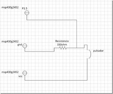
msp430g2452 4 pulsadores
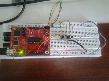
cuatro pulsadores msp430
#include
#define red_LED BIT6
#define BTN1 BIT3
#define BTN2 BIT0
#define BTN3 BIT5
#define BTN4 BIT4
int i1 = 0;
int i2 = 0;
int i3 = 0;
int i4 = 0;
void delay(void);
void main(void) {
WDTCTL
= WDTPW + WDTHOLD;
P1OUT =
0x00; //Turn off Red Led
P1DIR
= red_LED; // Set P1.0 as an output pin Red Led
while
(1) {
//especial
if((P1IN
& BTN1) == BTN1){
P1OUT
= red_LED; // turn on Red LED
}else{
P1OUT
= ~red_LED;
i1++;
__delay_cycles(300000);
}
if((P1IN
& BTN2) == BTN2){
P1OUT
= red_LED; // turn on Red LED
i2++;
__delay_cycles(300000);
}else{
P1OUT
= ~red_LED;
}
if((P1IN
& BTN3) == BTN3){
P1OUT
= red_LED; // turn on Red LED
i3++;
__delay_cycles(300000);
}else{
P1OUT
= ~red_LED;
}
if((P1IN
& BTN4) == BTN4){
P1OUT
= red_LED; // turn on Red LED
i4++;
__delay_cycles(300000);
}else{
P1OUT
= ~red_LED;
}
}
}
msp430 pulsadores y serial uart
java canvas msp430 pulsadores y serial uart
msp430 programa java para la interfaz canvas, conexión serial
import java.util.List;
import giovynet.nativelink.SerialPort;
import giovynet.serial.Baud;
import giovynet.serial.Com;
import giovynet.serial.Parameters;
import java.awt.*;
import java.applet.*;
public class main extends Applet {
static int x = 100;
static int y = 100;
public main() {
setSize(200, 200);
}
public void paint(Graphics g) {
try {
SerialPort serialPort = new SerialPort();
List portsFree;
portsFree = serialPort.getFreeSerialPort();
/**
* ** If there are free ports, use the first found. ***
*/
if (portsFree != null && portsFree.size() > 0) {
for (String free : portsFree) {
System.out.println("Free port: " + free);
}
/**
* **Open the port.***
*/
Parameters parameters = new Parameters();
parameters.setPort(portsFree.get(0));
parameters.setBaudRate(Baud._2400);
System.out.println("Open port: " + portsFree.get(0));
Com com = new Com(parameters);
/**
* **Open the port**
*/
g.setColor(Color.black);
g.fillOval(x, y, 50, 50);
String temp = "";
String temp2 = "";
for (int i = 0; i < 250; i = i) {
temp = com.receiveSingleString();
if (!(temp.compareToIgnoreCase("") == 0)) {
temp2 += temp;
if ((temp.compareToIgnoreCase(";") == 0)) {
System.out.println("lee: " + temp2);
if (temp2.compareToIgnoreCase("ar;") == 0) {
y-=10;
g.setColor(Color.white);
g.fillRect(0, 0, 200, 200);
g.setColor(Color.black);
g.fillOval(x, y, 50, 50);
}
if (temp2.compareToIgnoreCase("ab;") == 0) {
y+=10;
g.setColor(Color.white);
g.fillRect(0, 0, 200, 200);
g.setColor(Color.black);
g.fillOval(x, y, 50, 50);
}
if (temp2.compareToIgnoreCase("iz;") == 0) {
x-=10;
g.setColor(Color.white);
g.fillRect(0, 0, 200, 200);
g.setColor(Color.black);
g.fillOval(x, y, 50, 50);
}
if (temp2.compareToIgnoreCase("de;") == 0) {
x+=10;
g.setColor(Color.white);
g.fillRect(0, 0, 200, 200);
g.setColor(Color.black);
g.fillOval(x, y, 50, 50);
}
temp2 = "";
i++;
}
}
}
/**
* **Close the port.***
*/
System.out.println("\nfin");
com.close();
} else {
System.out.println("No Free ports!!!");
}
} catch (Exception e) {
e.printStackTrace();
}
}
}
fusion pulsadores y transmision seria uart msp430g2452
#include
// Pins on the MSP430 we're using
#define TXD BIT1 // TXD on P1.1
// Conditions for 2400 Baud SW UART, SMCLK = 1MHz
#define Bitime 13*4 // 0x0D
// variables for serial communication
unsigned char BitCnt;
unsigned int TXByte;
//botones
#define BTN1 BIT3
#define BTN2 BIT0
#define BTN3 BIT5
#define BTN4 BIT4
#define red_LED BIT6
// How many times have we pushed the button?
unsigned int buttonPresses = 0;
// function prototypes
void TXString(char *string);
void ConfigureTimerUart(void);
void Transmit();
void main( void )
{
// Stop watchdog timer to prevent time out reset
WDTCTL = WDTPW + WDTHOLD;
// Set clock to 1MHz, and SMCLK to 125kHz
BCSCTL1 = CALBC1_1MHZ;
DCOCTL = CALDCO_1MHZ;
BCSCTL2 &= ~(DIVS_3); //SMCLK is DCO/8
// Set up the timer to simulate a UART
ConfigureTimerUart();
__delay_cycles(1000000);
__enable_interrupt();
// Display the current button count, then go into LPM4. The button
// interrupt handler will turn the CPU back on which will bring us back
// to the beginning of the while() loop.
while(1)
{
////////////botones
//especial
if((P1IN & BTN1) == BTN1){
P1OUT = red_LED; // turn on Red LED
}else{
P1OUT = ~red_LED;
TXString("ar;");
__delay_cycles(300000);
}
if((P1IN & BTN2) == BTN2){
P1OUT = red_LED; // turn on Red LED
TXString("ab;");
__delay_cycles(300000);
}else{
P1OUT = ~red_LED;
}
if((P1IN & BTN3) == BTN3){
P1OUT = red_LED; // turn on Red LED
TXString("iz;");
__delay_cycles(300000);
}else{
P1OUT = ~red_LED;
}
if((P1IN & BTN4) == BTN4){
P1OUT = red_LED; // turn on Red LED
TXString("de;");
__delay_cycles(300000);
}else{
P1OUT = ~red_LED;
}
////////////botones
}
}
// Transmit a string via serial UART by looping through it and transmitting
// each character one at a time.
void TXString(char *string)
{
while(*string != 0)
{
TXByte = *string; Transmit();
string++;
}
}
// Set up timer for simulated UART. Copied from MSP430 LaunchPad sample code.
void ConfigureTimerUart(void)
{
TACCTL0 = OUT; // TXD Idle as Mark
TACTL = TASSEL_2 + MC_2 + ID_3; // SMCLK/8, continuous mode
P1SEL |= TXD; //
P1DIR |= TXD; //
}
// Function Transmits Character from TXByte
// Copied from MSP430 LaunchPad sample code
void Transmit()
{
BitCnt = 0xA; // Load Bit counter, 8data + ST/SP
while (TACCR0 != TAR) // Prevent async capture
TACCR0 = TAR; // Current state of TA counter
TACCR0 += Bitime; // Some time till first bit
TXByte |= 0x100; // Add mark stop bit to TXByte
TXByte = TXByte << 1; // Add space start bit
TACCTL0 = CCIS0 + OUTMOD0 + CCIE; // TXD = mark = idle
while ( TACCTL0 & CCIE ); // Wait for TX completion
}
// Timer A0 interrupt service routine
// Copied from MSP430 LaunchPad sample code
#pragma vector=TIMER0_A0_VECTOR
__interrupt void Timer_A (void)
{
TACCR0 += Bitime; // Add Offset to CCR0
if (TACCTL0 & CCIS0) // TX on CCI0B?
{
if ( BitCnt == 0)
TACCTL0 &= ~ CCIE; // All bits TXed, disable interrupt
else
{
TACCTL0 |= OUTMOD2; // TX Space
if (TXByte & 0x01)
TACCTL0 &= ~ OUTMOD2; // TX Mark
TXByte = TXByte >> 1;
BitCnt --;
}
}
}
led rgb
led rgb arduino parte 1
Processin
---------------------------------------------------
import oscP5.*;
import netP5.*;
import processing.serial.*;
OscP5 oscP5;
Serial serial;
Fader fdrRed;
Fader fdrGreen;
Fader fdrBlue;
int r, g, b;
void setup() {
size(600, 320);
smooth();
//Se crea el objeto OSC en el puerto 8000
oscP5 = new OscP5(this, 8000);
//abrir el puerto serial
try {
serial = new Serial(this, Serial.list()[0], 9600);
}
catch(Exception e) {
println("Can't open port...");
}
//Crear los faders
fdrRed = new Fader(10, 10, 'R');//px, py, color
fdrGreen = new Fader(90, 10, 'G');
fdrBlue = new Fader(170, 10, 'B');
}
void draw() {
//draw the faders
fdrRed.draw();
fdrGreen.draw();
fdrBlue.draw();
//Guardar cada valor del fader con su valor en el grafico
r = fdrRed.getValue();
g = fdrGreen.getValue();
b = fdrBlue.getValue();
//Escribir el puerto serial
try {
//escribe la clave delcolor rojo y el valor de [0-255]
serial.write(10);
serial.write(r);
//escribe la clave delcolor verde y el valor de [0-255]
serial.write(20);
serial.write(g);
//escribe la clave delcolor azul y el valor de [0-255]
serial.write(30);
serial.write(b);
}catch(Exception e) {
println("Can't write serial port...");
}
//dibuja el rectangulo con el color resultante del led rgb
stroke(0);
fill(color(r, g, b));
rect(270, 10, 300, 300);
}
class Fader {
int val, valMap;
int px, py;
final int h=300, w=70;
color[] col;
color[] red= {
color(#DE1D2A), color(#131010), color(#501515)
};
color[] green= {
color(#3B811C), color(#111410), color(#25451A)
};
color[] blue= {
color(#1C2D81), color(#0D0D10), color(#0C1233)
};
Fader(int px, int py, char c) {
this.px=px;
this.py=py;
switch(c) {
case 'R':
col=red;
break;
case 'G':
col=green;
break;
case 'B':
col=blue;
break;
}
setValue(0);
}
void draw() {
strokeWeight(4);
strokeJoin(ROUND);
stroke(col[0]);
fill(col[1]);
rect(px, py, w, h);
fill(col[2]);
rect(px, py+(h-valMap), w, valMap);
if (mousePressed && (mouseX >= px && mouseX <= px+w) && (mouseY >= py && mouseY <= py+h)) {
setValue((int)map((h-(mouseY-py)), 0, h, 0, 255));
}
}
void setValue(int val) {
this.val=val;
valMap=int(map(val, 0, 255, 0, h));
}
int getValue() {
return val;
}
}
led rgb parte 2
int intCase = 0;
int leds[]={2, 3, 4};//pines de los leds
int led;//led a midificar
boolean cambiando=0;//bandera para recibir datos
const int ledCom=13; //led indicador
void setup(){
for (int i = 0, t = sizeof(leds); i < t; i++) {
pinMode(leds[i], OUTPUT);
}
pinMode(ledCom, OUTPUT); //indicator salida
Serial.begin(9600);
}
void loop(){
//si esta habilitado la salida de datos en el buffer del puerto
if (Serial.available() > 0) {
intCase = Serial.read();
if (cambiando){
//modifica la intensidad del led
analogWrite(leds[led], intCase);
//resetea el valor de la bandera y el led indicador
cambiando = false;
digitalWrite(ledCom, LOW);
}else /*si no */{
//seleciona el led a modificar y activar la bandera para que lo escriba
switch (intCase){
case 10://r
led=0;
digitalWrite(ledCom, HIGH);
cambiando=1;
break;
case 20://g
led=1;
digitalWrite(ledCom, HIGH);
cambiando=1;
break;
case 30://b
led=2;
digitalWrite(ledCom, HIGH);
cambiando=1;
break;
}//switch
}//fin else
}//fin if
}//fin loop
Motor DC
morto dc arduino
int potpin = A0;
int val;
void setup() {}
void loop() {
val = analogRead(potpin);
val = map(val, 0, 1023, 0, 225);
analogWrite(3, val);
delay(15);
}
servo motor
servo motor
#include
•
Servo myservo; // crea un objeto tipo servo para controlar el servo
• int pos = 0; // variable para almacenar la posición del servo
//------------------------------------------------------------------------------------------
// set pin numbers:
• const int buttonPinFront = 10; // the number of the pushbutton pin
• const int buttonPinBack = 11; // the number of the pushbutton pin
• const int ledPin = 13; // the number of the LED pin
•
// variables will change:
• int buttonStateFront = 0; // variable for reading the pushbutton status
• int buttonStateBack = 0; // variable for reading the pushbutton status
//------------------------------------------------------------------------------------------
int i;
•
void setup() {
•
myservo.attach(9); // liga el servo conectado en el pin 9 al objeto servo
//------------------------------------------------------------------------------
// initialize the LED pin as an output:
pinMode(ledPin, OUTPUT);
// initialize the pushbutton pin as an input:
pinMode(buttonPinFront, INPUT);
pinMode(buttonPinBack, INPUT);
//------------------------------------------------------------------------------
for (i = 2; i <= 9; i++) {
pinMode(i, OUTPUT);
}
//------------------------------------------------------------------------------
Serial.begin(9600);
moved(0, 0);
}
•
void loop(){
•
buttonStateFront = digitalRead(buttonPinFront);
buttonStateBack = digitalRead(buttonPinBack);
•
switch (buttonStateFront) {
case HIGH:
Serial.print(" > ");
moved(1, 0);
break;
}
•
switch (buttonStateBack) {
case HIGH:
Serial.print(" < ");
moved(0, 1);
break;
}
}
•
void moved(int subir, int bajar){
•
if(subir){ if(pos < 6) pos++; }else if(bajar){ if(pos > 0) pos--; }
•
apagarVarios(pos + 2, 2, 9, 100);
myservo.write(pos * 30);
•
Serial.print(pos, DEC);
Serial.print(' ');
Serial.println(pos * 30, DEC);
delay(250);
•
}
•
boolean apagarVarios(int pin, int i, int j, int tiempo) {
•
for (; i <= j; i++) {
if (pin != i) {
apagar(i);
} else { encender(pin, tiempo); }
}
return true;
}
•
void encender(int pin ,int tiempo){
digitalWrite(pin,HIGH);
delay(tiempo);
}
•
void apagar(int pin){
digitalWrite(pin,LOW);
}
Reproducción de una canción en un Piezo (Buzzer) o un Speaker.
Reproducción de una canción en un Piezo (Buzzer) o un Speaker.
int speakerPin = 6;
int length = 15; // the number of notes
char notes[] = "bdbbdbebdebdeafgagebacb "; // a space represents a rest
int beats[] = { 1, 1, 1, 1, 1, 1, 2, 1, 1, 1, 1, 1, 1, 2, 4 };
int tempo = 300;
void playTone(int tone, int duration) {
for (long i = 0; i < duration * 1000L; i += tone * 2) {
digitalWrite(speakerPin, HIGH);
delayMicroseconds(tone);
digitalWrite(speakerPin, LOW);
delayMicroseconds(tone);
}
}
void playNote(char note, int duration) {
char names[] = { 'c', 'd', 'e', 'f', 'g', 'a', 'b', 'C' };
int tones[] = { 1915, 1700, 1519, 1432, 1275, 1136, 1014, 956 };
// play the tone corresponding to the note name
for (int i = 0; i < 8; i++) {
if (names[i] == note) {
playTone(tones[i], duration);
}
}
}
void setup() {
pinMode(speakerPin, OUTPUT);
}
void loop() {
for (int i = 0; i < length; i++) {
if (notes[i] == ' ') {
delay(beats[i] * tempo); // rest
} else {
playNote(notes[i], beats[i] * tempo);
}
// pause between notes
//delay(tempo / 2);
}
}
Control de 8 LEDs con un IC 74HC595 (Shift Register).
Control de 8 LEDs con un IC 74HC595 (Shift Register).
/*
Shift Register Example
for 74HC595 shift register
This sketch turns reads serial input and uses it to set the pins
of a 74HC595 shift register.
Hardware:
* 74HC595 shift register attached to pins 2, 3, and 4 of the Arduino,
as detailed below.
* LEDs attached to each of the outputs of the shift register
Created 22 May 2009
Created 23 Mar 2010
by Tom Igoe
*/
//Pin connected to latch pin (ST_CP) of 74HC595
const int latchPin = 8;
//Pin connected to clock pin (SH_CP) of 74HC595
const int clockPin = 12;
////Pin connected to Data in (DS) of 74HC595
const int dataPin = 11;
void setup() {
//set pins to output because they are addressed in the main loop
pinMode(latchPin, OUTPUT);
pinMode(dataPin, OUTPUT);
pinMode(clockPin, OUTPUT);
Serial.begin(9600);
Serial.println("reset");
}
void loop() {
if (Serial.available() > 0) {
// ASCII '0' through '9' characters are
// represented by the values 48 through 57.
// so if the user types a number from 0 through 9 in ASCII,
// you can subtract 48 to get the actual value:
int x=Serial.read();
Serial.print("Numero: ");
Serial.println(x);
// write to the shift register with the correct bit set high:
enviarChar(x);
}
}
//Envia un caracter para ser mostrado con los leds
void enviarChar(int num){
int z=0;
for(char i=0; i<8; i++){
//Enmascaramos el dato para dejar solo el bit mas significativo
z=num & B1000000;//z sera 0 o 128
//Enviamos el bit dependiendo de z
if(z==0){
enviar(LOW);
}else{
enviar(HIGH);
}
//Desplazamos el numero un bit a la izquierda
num=(num << 1);
}
}
//Envia un bit al 74HC
void enviar(int estado){
//Colocamos el dato en la salida del micro, en el pin de datos
digitalWrite(dataPin, estado);
//Almacenamos lo que hay en el pin de datos en el latch del IC mandando un pulso
digitalWrite(latchPin, HIGH);
digitalWrite(latchPin, LOW);
//Desplazamos los datos colocando un pulso en el pin de clock
digitalWrite(clockPin, HIGH);
digitalWrite(clockPin, LOW);
}
Reloj Digital usando una pantalla LCD, y un IC DS1307
Reloj Digital usando una pantalla LCD, y un IC DS1307.
/*
*/
// include the library code:
#include
// initialize the library with the numbers of the interface pins
LiquidCrystal lcd(12, 11, 7, 6, 3, 2);
int minutos=59;
int segundos=50;
int horas=0;
int milis=0;
void setup() {
// set up the LCD's number of columns and rows:
lcd.begin(16, 2);
// Print a message to the LCD.
lcd.print("HORA:");
}
void loop() {
// set the cursor to column 0, line 1
// (note: line 1 is the second row, since counting begins with 0):
lcd.setCursor(0, 1);
// print the number of seconds since reset:
segundos++;
if(segundos>59){
minutos++;
segundos=0;
}
if(minutos>59){
horas++;
minutos=0;
}
if(horas<10)lcd.print("0");
lcd.print(horas);
lcd.print(":");
if(minutos<10)lcd.print("0");
lcd.print(minutos);
lcd.print(":");
if(segundos<10)lcd.print("0");
lcd.print(segundos);
delay(1000);
}
Control de un Motor Stepper con un IC ULN2003
Control de un Motor Stepper con un IC ULN2003.
int paso=0;
int pines[] = {4, 5, 6, 7};
int secuencia[8][4] = {{1,0,0,0},{1,0,1,0},{0,0,1,0},{0,1,1,0},{0,1,0,0},{0,1,0,1},{0,0,0,1},{1,0,0,1}};
const int buttonPinMas = 9;
const int buttonPinMenos = 10;
void setup() {
for(int i=0; i7)
paso=0;
else if(paso<0)
paso=7;
for (int i = 0, t = sizeof(pines); i < t; i++){
Serial.print(pines[i]);
digitalWrite(pines[i],secuencia[paso][i]);
}
Serial.println();
}
int pines[] = {4, 5, 6, 7};
int secuencia[8][4] = {{1,0,0,0},{1,0,1,0},{0,0,1,0},{0,1,1,0},{0,1,0,0},{0,1,0,1},{0,0,0,1},{1,0,0,1}};
const int buttonPinMas = 9;
const int buttonPinMenos = 10;
void setup() {
for(int i=0; i
paso=0;
else if(paso<0)
paso=7;
for (int i = 0, t = sizeof(pines); i < t; i++){
Serial.print(pines[i]);
digitalWrite(pines[i],secuencia[paso][i]);
}
Serial.println();
}